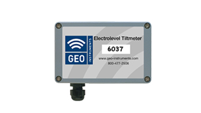
Electrolevel Tiltmeters
Electrolevel tiltmeters are used to monitor small changes in inclination. They are ideal for monitoring structural rotation, differential settlements, deformation, and convergence. Datasheet

Applications
- Monitoring the stability of structures adjacent to excavations.
- Monitoring deformation of shoring walls.
- Monitoring the tilt of piers and piles.
- Monitoring differential settlements.
- Monitoring deformation in tunnels.
- Monitoring compensation grouting in real time.
Mounting Methods
Brackets: Tiltmeters are fixed to the structure via mounting brackets. The flat bracket holds the tiltmeter parallel to the mounting surface. The right-angle bracket holds the tiltmeter 90 degrees to the mounting surface. The right- angle bracket is also used to mount tiltmeters on floors and ceilings.
Beams: Tiltmeters can also be mounted on low-profile beams to monitor relative movement between anchor points at either end of the beam. An array of beams, each sharing an anchor point with the next, can be used to monitor differential settlements, deformations, and convergence.
Standard or Digital Interface
In the standard configuration, each tiltmeter is supplied with a length of cable that runs from the tiltmeter to the data logger. For example, six tiltmeters require six cables.
When an array of many tiltmeters is required, management of cables and connections to the logger can be difficult. For such cases, the tiltmeters can be supplied with a Digital interface and interconnected with an RS-485 multidrop bus cable. This simplifies cabling and connections.
Advantages
High Resolution: The tiltmeter detects changes as small as one second of arc.
Proven Technology: Electrolevel sensors are robust and reliable with minimal electronic components.
Digital Interface: The optional digital interface simplifies cable management and connections to the logger.
Versatile: Electrolevel tiltmeters are compact and can be installed in nearly any location.
Cost Effective: Electrolevel tiltmeters provide reliable, high resolution readings at a competitive price.
Analog Tiltmeter Specifications
Sensor Type: Electrolytic. Uniaxial tiltmeter contains one sensor, Biaxial tiltmeter contains two sensors.
Full Range: ± 3°.
Calibrated Range: ± 0.68° or 12 mm/m.
Resolution: 1 arc second or 0.005 mm/m.
Accuracy: <1% FS (calibrated range).
Temp Rating: -20 to +50 °C.
Enclosure: IP 66, powder-coated metal.
Dimensions: Uniaxial enclosure measures 4.9 x 3.2 x 2.3" (125 x 80 x 59 mm).
Compatibility: Campbell Scientific Loggers.
Installation Accessories
Zeroing Device
Used at installation time to level the tiltmeter. Compatible with both standard and digital tiltmeters.
Mounting Brackets
Flat, for uniaxial tiltmeter
Flat, for biaxial tiltmeter
Right-angle, for uniaxial
Right-angle, for biaxial
Beams & Anchors
Beams include end brackets and wall anchors.
3 foot beam
6 foot beam
Digital Tiltmeters
Digital Tiltmeter, Uniaxial
Specifications and accessories are the same as standard tiltmeters except as noted below.
Bus Type: RS485.
Bus Cable: 2 twisted pairs, 22 gauge.
Supply Voltage: 5 -12 Vdc.
Supply Current: 9 mA @5 Vdc, 6 mA@ 3.3 Vdc. Max Addresses: 99.
Max Sensors on Bus: 32.
Max Bus Length:
4000 feet with up to 24 sensors.
3408 feet with 25 sensors.
3218 feet with 30 sensors.
3017 feet with 32 sensors.
Digital Tiltmeter Accessories
Bus Cable
Bus cable to connect each tiltmeter to the next and finally to the logger.
Connectors
A pair of connectors are required for each length of bus cable. No connector is needed at data logger.
Termination Resistor
One termination resistor per bus is required.
485 to 232 Interface Module
One 485-to-232 interface per bus is required.
