I-5 Undercrossing for Sound Transit

This wide-angle photo shows excavation of one of the four pits (left), a scan station (middle), and one of the 400-foot long retaining walls (background).
Project Overview
Sound Transit’s U-Link project extends the regional light-rail system from downtown Seattle to the University District, via a 3.5 mile tunnel. The most complex and highest risk section of the project was U215, where the tunnel crosses under I-5. GEO-Instruments was selected to monitor the project and succeeded in installing and commissioning the system in just four weeks. Instrumentation included the first use of an automated pulse laser scanner for geotechnical monitoring.
At the location of the undercrossing, the highway is bordered by 40-foot high retaining walls, each 400 feet long, on either side of the highway. The TBM would damage the deep foundations of these walls unless they were modified. U215 specified the modification process, which involved excavating four deep pits, cutting windows into the foundations, reinforcing the windows, and then concreting the pits in preparation for the TBM.
Monitoring Requirements
To help manage the risks, design engineers wanted to monitor any movement of the walls during the modification process and then monitor the performance of the walls during and after tunneling. To be useful, the monitoring system would have to provide near-real time data. GEO-Instruments was selected to provide this service and succeeded in installing and commissioning the system in just four weeks.
Instrumentation
Instrumentation included tiltmeters for monitoring rotation, beam sensors for monitoring surface deformations, inclinometers for monitoring subsurface deformations, and AMTS for 3D point measurements. Six data loggers collected readings, which were then forwarded to a web-based database.
Laser Scanner
The designers also requested that laser scanners be integrated into the monitoring system. This would be the first use of a pulsed laser scanner for a geotechnical application. GEO-Instruments implemented an automated laser scanner system to make full scans of both walls twice per day. To make the scans useful for geotechnical monitoring, scan targets were placed in precise vertical arrays at 10 locations. These allowed calculations of vertical displacements and also served as reference points for the scans. An on-site computer ran a specially written program to provide least-square corrections and calculations of vertical profiles for upload to the project database.
Other Unique Features
Other unique features of the instrumentation system included a network of wireless tiltmeters that relayed their data from unit to unit across 400 feet of highway, solar powered in-place inclinometers, and multiple paths for data retrieval (DSL and cellular).
Benefits of instrumentation
The combination of laser scanners, AMTS, tiltmeters, and IPIs provided accurate data and useful redundancy to help ensure a safe, secure working environment and successful completion of the project.
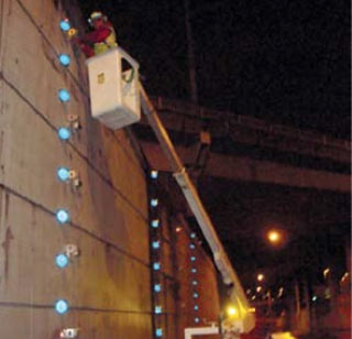
GEO-Instruments installed 250 scan targets.
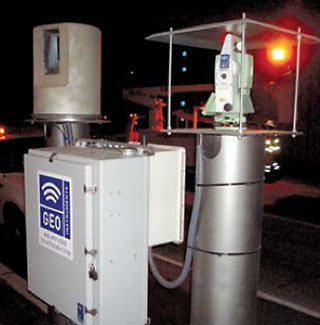
Laser scanner in carbon-fiber protective enclosure (left) and AMTS, along with enclosures for logger and PC.
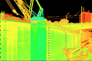
Targets are visible in this laser scan image. A custom PC application processed scans to provide numeric data.
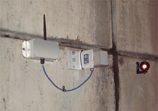
Wireless tiltmeters relayed readings across 400 feet of highway. Prism for AMTS was installed at the same location.
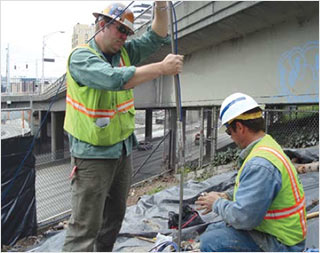
Installing In-Place Inclinometers to monitor subsurface movements.
