Multi-level Piezos at SR12
Caltrans Bay Area is improving a complex highway interchange involving I-80, I-60, and SR12, replacing a bridge and building dedicated connectors and off ramps to reduce congestion. GEO installed multi-level piezometers to monitor the progress of consolidation before construction begins.
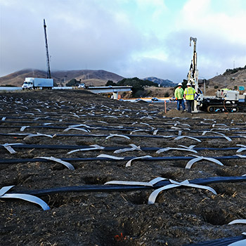
Ground improvement is required before this SR12 ramp can be widened. Keller installed wick drains at this location.
GEO was contracted to install two multi-level piezometers to monitor the progress of consolidation.
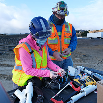
The piezometers for this project were designed to be installed in-line with PVC pipe, with cables running inside the pipe.
Each piezometer was supplied with 200 feet of cable, long enough to reach a data logger outside the work area.
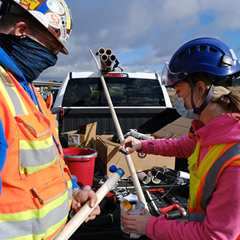
Piezometer depths were 60, 35, and 17 feet for both installations.
Appropriate lengths of PVC pipe were prepared and color coded to match the piezo housings for error-free assembly. Piezo housings were not attached yet.
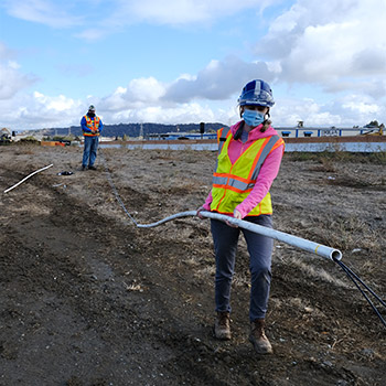
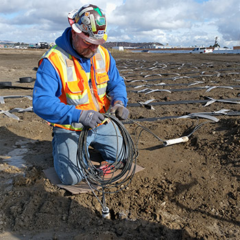
Rather than push and pull 200 foot cables through each of the PVC pipes, GEO arranged the piezo housings near the drill rig and layed out their cables in parallel lines. At the far end, the PVC pipes were slipped onto the appropriate cables and walked toward the piezo housings, as shown above.
Afterwards, piezo housings were cemented onto the pipes.
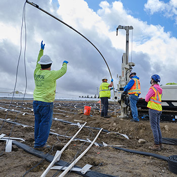
The bottom piezo and its attached pipe are inserted into the drill casing. The middle piezo, seen at the top of the photo, was also cemented to this pipe for easier handling later.
Slack cable allows the pipe to be lifted fully vertical for installation.
The next two lengths of pipe are lined up, ready for the installer.
Drillers had to advance drill casing to the bottom of the borehole because the lower depths would not stay open.
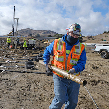
After the piezometers were installed, the drill casing had to be removed. This photo shows a casing joint removed from the borehole and being walked to the end of the cable.
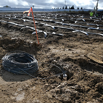
The pipe was cut off at grade as requested by the owner. The first installation is completed except for grouting. At top right, the driller is setting up for the next hole.
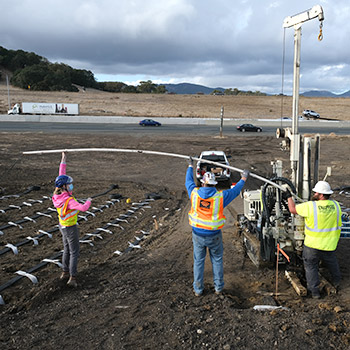
The same steps were followed for the second installation. The photo above shows the last length of pipe being installed.
The pipe is cut off at grade again. The black tape just visible at the top of the pipe marks exactly 60 feet from the piezo at the bottom.
